NASA Space Simulation Software - OpenSpace
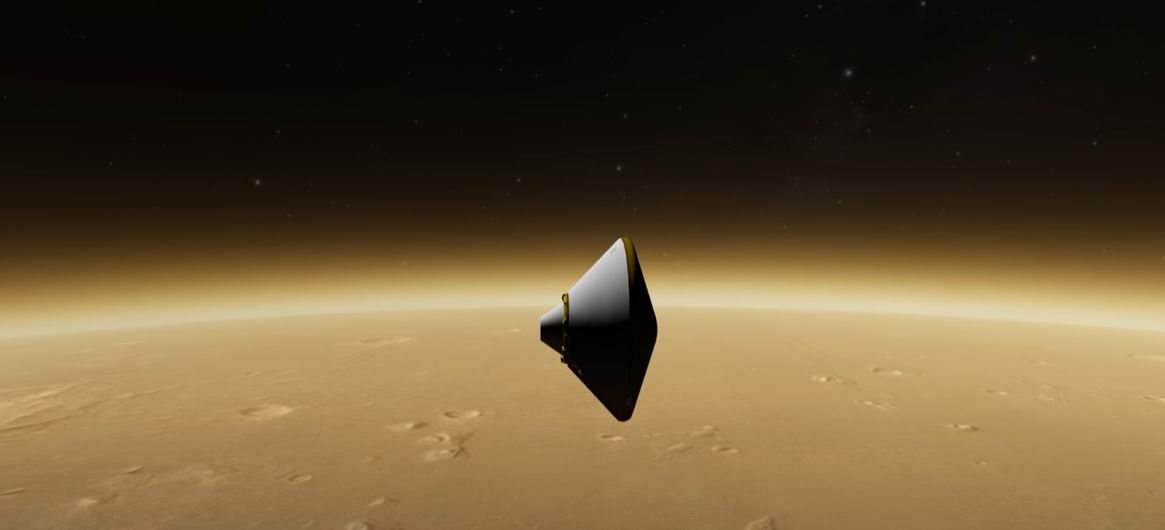
To support NASA’s space research efforts as well as drive further interest towards general astronomy, OpenSpace is designed to visualise the entire known universe and mankinds ongoing efforts of investigating the cosmos. The software system originates from an academic collaboration and capable of modelling space weather forecasting, visualize NASA’s New Horizons mission to Pluto and ESA’s Rosetta mission. Further, utilising NASA’s SPICE observational geometry system with its Planetary Data Service (PDS) can space missions be visualised to evoke interest and portray how science is gathered.
With many ongoing initiatives, our project with OpenSpace was limited to develop multi-touch interfaces to allow more public and intuitive interaction with the digital universe we were creating in a similar sense to how people operates their everyday devices; touch. Touch based interactions are typically in 2D and have the expectations to be designed by direct-manipulation, meaning to give the user the feeling of interacting with real objects. As the user moves their fingers along the touch surface, virtual objects rotate, translate and scales appropriately such that the object or area always remains underneath the fingertips. This type of Rotate-Scale-Translate (RST) interaction has become the de-facto standard in 2D touch environments to provide intuitive and controllable mapping between points in an object’s local space and points in screen space without the need for any explicit gesture processing. Higher dimensional manipulation faces a challenge since it involves the control of an increasing numbers of degrees of freedoms (DOF) with an increased complexity and persisting limitation of a 2D input device. Further, interacting with astronomical visualisations and real world distances between celestial bodies pose the sheer scale as a challenge. Direct-manipulation alone cannot solve interaction when, in many situations, the viewplane will be completely without visible objects to touch. We proposed a novel approach by intertwining a Screen-Space direct-manipulation formulation together with a velocity based model seamlessly to explore both close and far away from surfaces of celestial bodies.
Direct manipulation
Choices in DOF Separation
To allow control over a celestial body from a space perspective as well as a street-view perspective, the chosen direct-manipulation formulation had to be the screen-space method by Reisman et al. While Reisman’s arrangement works beautifully in the control of an object’s six degrees of freedom, OpenSpace instead aims to move the camera state, and thus its view plane, rather than the celestial bodies themselves. Due to the vastness of space and inexplicit direction of up and down, all camera movements have been designed such that it is always done in relation to a body in focus. This naturally creates a new set of DOF’s which allows the user to freely traverse with the camera through space while keeping the focus in context.
- Orbit - contains two euler angles, θ and ϕ, to decide the camera’s position and look-at direction related to the focused celestial body.
- Zoom - single value related to the distance to the focus.
- Roll - contains one angle value that determines the roll orientation of the camera.
- Pan - consists of two angles that determine the local look direction of the camera itself
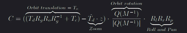
To achieve this, the camera orientation matrix Q needs to be separated in local and global rotations using a look-at matrix with the camera location, the face direction as well as the up-direction and compute a resulting matrix L. L can then be used to separate Q by defining a global rotation Rg = normalized(L^-1) and a local rotation Rl = Rg^-1 such that Q = Rg · Rl. The equation below is then a three-part way to describe the desired DOF separation. The first part calculates the rotation and translation transformations from the orbit DOF, second the zoom translation and third the local orientation of the camera, ie. roll and pan. The translation terms from the orbit and zoom are merged for notational compactness.
 in which Q(M) is the quaternion of the 4 x 4 look-at matrix
 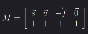 where
where f = To, s = f · (Rg · [0, 1, 0]) and u = s · f. Rg and Rl are defined as above, Td = T - Tf is the distance matrix between the camera position and the celestial body in focus. To is the translation part of the orbit-interaction while Ro is the rotation quaternion built from the orbit angles. Lastly Rr and Rp are quaternions gotten from the roll and pan angles respectively.
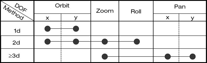
With this formulation it is now clear how the camera state changes dependant on the newly defined DOF separation. The resulting control implementation into OpenSpace can be seen in the figure above, where 1d represents one active contact point on the surface of a virtual object, 2d two, etc. The >3d case generally has control over all six parameters, however the orbit and roll DOF were muted by normalising their individial partial derivatives to keep interface inline with the velocity-based model.
Creating the minimise function and its gradient
The Levenberg-Marquardt algorithm is at the core of direct-manipulation interaction and is used as a non-linear least-square curve fitting solver. As the algorithm interpolates between the Gauss-Newton algorithm (GNA) and gradient descent, it naturally requires the gradient of the function that is subject to be minimised to operate. Reisman et al. defines a function 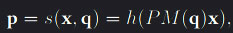 which maps the local point x to world coordinates to later be projected back to screen-space for location comparison with its respective contact point. h is is the view matrix, P the projection matrix and M a matrix parameterised by the vector q which maps x into world-space. M is a combination of several rotation, translation and scaling matrices. By keeping the projection matrix P constant, the only way to alter a model view point’s corresponding point in screen-space is by the local to world-space transformation, as no change is done to any of the camera’s DOF. Using a difference scheme as Gleicher et al. we can define the best-fit transform parameters M(q) by minimising the non-linear L^2 error fuction that measures the total squared distance between the contact points’ screen-space projection and their corresponding screen-space target positions. The error is defined as
 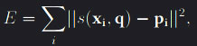 where xi and pi are the positions of the ith object-space contact point and screen-space target points respectively and the minimisation of E is with respect to q, the vector defined by the six degrees of freedom such that
 q = [tx, ty, tz, rx, ry, rz].
The main difference from the definitions above with our implementation is that the transformation M(q) parameterised by the DOF vector is not applied to the virtual object itself. The point x remains constant while instead the camera position and orientation, and thus the view plane to which x will be projected back to, is changed according to the equation C(q) above. As such, the minimisation function becomes 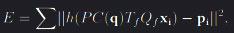 where Tf and Qf are translation and rotation transformation that maps point x from its local view to world coordinates. P is the projection matrix, pi the corresponding screen-space point, C(q) as defined above and h the function that converts the 3D point to screen-space coordinates. E is minimised with respect to the vetor q that is constructed by the parameters controlling the different DOF. Depending on the type of interaction, q thus contains two, four or six elements.
A question that arise is how the function’s gradient changes dependant to q. An analytical solution for this becomes complex as the statement is non-linear and contains transforms between 3D to 2D into a scalar value. Instead, a forward Euler method scheme is used such that 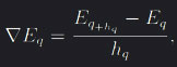 where step size hq is a fraction of the respective value in q. This means that the step size for the partial derivative changes as the DOF the function is derived with respect to changes. Due to the large size differences in astronomical datasets, this raises a computer numerical limitation in the choice of step size hq. Interactions under a street-view distance with a small asteroid or at distances approaching an astronomical unit (A.U) should feel just as natural to the user. The extreme variance in interaction motion causes the parameters in q to fluctuate massively. For example, the zoom parameter z in q determines the distance the camera should move towards or away from the focus. The identical interaction gesture on a large celestial body generates a greater traversed distance in depth compared to an asteroid, resulting in vastly different z values. To keep the gradient
 ∇Eq convergent, the minimal step size hq must be large enough such that its numerical difference D = |Eq+hq − Eq| > 0 can be quantified. It is also a topic of importance for optimisation as the number of iterations LMA requires to converge can drastically be reduced with an appropriately defined numerical gradient. A large step size makes the LMA more prone to overstep resulting in an increased number of iterations, while a step size small enough to generate a next to indistinguishable difference D faces the opposite problem of taking too small steps. The local minima is somewhere in between however to adjust the stepsize analytically in each LMA iteration is not feasible, as such we implemented an iterative method to find the fitting step size by scaling the minimum viable step size according to the size of the interacted object.
Finding selected objects
In order to perform any type of minimisation, the local 3D point x is required. This point is generated through general ray trace by sending a vector from the camera, through the contract point in screen-space and into the 3D scene. 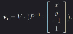 where V and P are the view and projection matrices respectively and x and y the contact point’s coordinates on the image screen. All celestial bodies in OpenSpace have a rough bounding volume estimated by the object’s radius, which allows for several methods to find if and where intersections occur between the line in the ray direction v and an objects in the scene. If v0 is the vector from the camera position c pointing towards an objects position p, then one way to define the distance between the line and the object is through orthogonal projection. Note that v is the direction of the traced line with the camera position on it and of unit length one. Another, more efficient method, is to use the area of the parallelogram formed by the vector v0 and v. If the shortest interval between point p and the projected line is then less or equal to the bounding sphere’s radius r an intersection is considered,
 |v x v0| < r. Disregarding the case where v is the tangent to the bounding sphere, there will always be two intersection points along the traced line while only the closest point with respect to the camera is desired. We can traverse a distance t through the ray to determine the closest intersection point and thus find the desired local 3D point x by 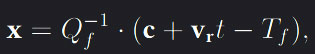 where Q and T are the translation and rotation matrices that transforms a point from its local view to world coodrinates. This step is done to ensure that a surface position on an object remains static, since its’ world coordinates will change with regards to time.
Implementation
Decoupling the Input
We implemented multi-touch input support to the application through the TUIO protocol, which works through server-client transmissions. This approach, along with TUIO being cross-platform, allowed us to create support for touch input through any type of touch surface - be it via an app on your iPhone/Android phone or a 55” touch-table running any OS, we could take control and navigate through the digital universe with it. With an integrated server listening for input, it becomes important to decouple the received input from the simulation loop as otherwise touch interaction would vary depending on what system the application was run on.
Determine type of interaction scheme
In regards with what to do with the input, it must first be settled which interaction scheme is to be used. The velocity-based model is implemented to handle the cases the screen-space solver cannot. First the method interprets the type of interaction to then add a velocity to the desired DOF and decelerate with time using a chosen friction value. An important aspect with intertwining two interaction schemes is to automatically and seamlessly swap between them. Direct-manipulation can be used in all cases where every active contact point (fingers) touches a virtual object, however it falls short when generally traversing through the vastness of space. This since during those interactions there is no contact with celestial bodies and thus no local 3D point x can exist. Velocity-interaction struggles with scaling values deciding the magnitude of the velocity when the context changes drastically. Getting appropriate scaling values when the context can vary from a detailed street-view of Earth to traversing through the entire solar system with the swipe of ones fingers is not a trivial task. A decision solver was implemented to elect the type of interaction scheme based on two queries:
- Are all contact points on the surface of a virtual object?
- Is the focused object large enough on the screen?
If both are true, direct-manipulation can be used while the velocity-method takes all other cases. The first condition can be determined through the method explained above, however the second depend upon a size definition of an object in image space. Since the object’s radius r in the world is known and the projection matrix P scales objects depending on the distance to the camera can the scaling coefficients be found by choosing an arbitrary vector v as well as an arbitrarily choosen distance d. The scaling value s can be defined as 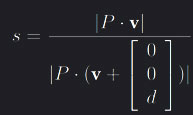 . An object-specific screen radius Rs can thus be defined as
 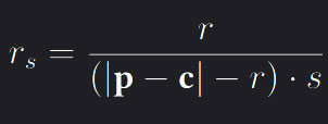 where p and c are the positions of the object and camera respectively and r is the original radius of the celestial body. r is used in the denominator to measure the distance between the camera and an object’s surface rather than its center,
 Rs ∈ [0, r] defines the star, planet or asteroid’s size on the image screen. As the view plane is defined in normalised device coordinates (NDC) before aspect ratio distortions, an object with Rs = 0.5 would cover the entire y-plane on parts of the screen. The threshold h which Rs > h to activate direct-manipulation can be chosen readily by the user however default to h = 0.2 gave good results.
Interaction types and interpretation
In order to apply a velocity to the desired DOF the input has to be interpreted and classified to a distinct interaction. In our implementation, there are five kinds of gesture interpretations:
- Refocus on a celestial body can be done by double tapping, alternatively a double tap in space decreases the distance between the camera and the focused object by a fixed about.
- Orbit control around the focus is done by single finger interaction.
- The zoom DOF is controlled by two or more contact point with the preponderance motion of increasing the distance between a contact point and their centroid.
- The roll value determined by the total angle change between contact points and their centroid or a static contact point.
- Panning is done by having three active contact points which average distance between each other remains constant.
Velocity-based Method
After interpreting the type of gesture, the motion of the input are used as the main variable determining the magnitude of the added velocity in the determined DOF direction. Each DOF requires a sensitivity scalar in order to ensure consistency with different screen sizes and aspect ratios. The zoom DOF is particularly interesting as its expected velocity value largely depends on the context the pinch-gesture is performed with. Keeping sensitivity static would either make interaction illsupoprted when traversing from one celestial body to another or when the camera moves closer. Using the distance between an objects surface and the camera position as a linear scale factor resolves cases where the distance is large to medium, however the issue remains on distances comparable the radius of the sun.
As the interaction adds velocity, to prevent infinite movement this has to decay with time. DOF specific friction parameters were introduced to control this deceleration. This friction deceleration computation is done once for each frame, which caused inconsistency in the velocity deceleration between different systems or inconsistent render times. The deceleration was thus decoupled from the frame time by introducing a time tracker where by each frame, the time since last computation is considered to determine the amount the velocity should decelerate such as  where f is the friction scalar and λ the strength of decay controlled by time.